Overview
Capacitive loading was a condition axis in the test matrix, applied across many DVT tests. Electronic loads handle resistive and constant-current profiles, but switching capacitor banks needs relay control with different safety constraints. Rather than rig something up manually each time, I built a simple USB-controlled switch that the ATE could drive like any other instrument.
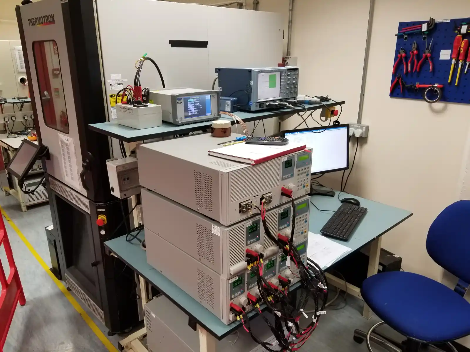
The device is straightforward: two relay channels on an ATmega, one for connecting the unit under test and one for switching the capacitive load. It sat on the bench alongside commercial instruments from Chroma, Kikusui, and LeCroy, controlled through the same ATE framework.
The Circuit
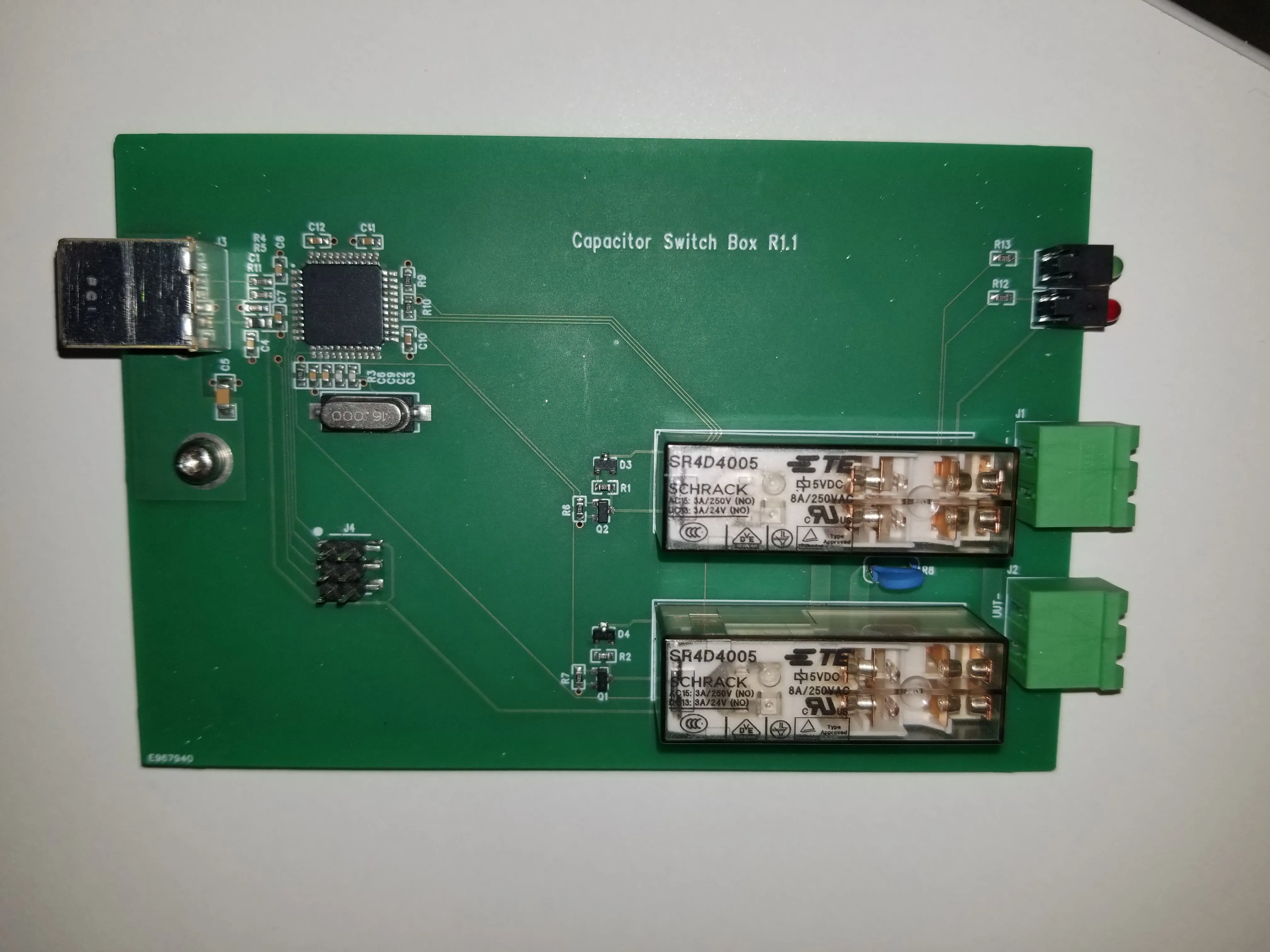
An ATmega microcontroller driving two Schrack relays. Relays rather than solid-state switches because capacitive inrush currents are substantial, and galvanic isolation keeps the load path separate from the control circuitry. The C++ firmware runs a state machine that listens for commands over USB serial: open channel, close channel, query state.
The firmware is intentionally minimal. All the intelligence lives in the VB.NET test software, which treats this through the same driver abstraction layer as every other instrument on the bench.
Prototype to Production
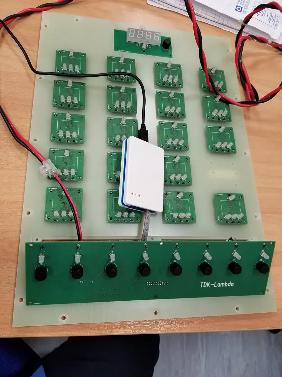
The first version was an Arduino Nano on stripboard, hand-wired to relays, powered from USB. Good enough to validate the concept and run initial tests, but fragile: hand-soldered connections, too large for permanent bench installation, and not reliable enough for overnight unattended runs.
I designed a custom PCB with the same ATmega chip and the same firmware (zero code changes), in a compact form factor with proper connectors. The PCB version became a permanent fixture on the test bench.
ATE Integration
I wrote a VB.NET driver following the same pattern as the Chroma, Kikusui, and LeCroy drivers in the ATE framework. Test code couldn't tell the difference between commanding this custom PCB and a commercial instrument.